


Industrial Control Transformers: Complete Guide
 June 10, 2026
An industrial control transformer is a step-down isolation transformer built specifically to power the control circuits inside industrial machinery.
It takes a high-voltage primary supply – typically 220 V, 480 V, or 600 V – and delivers a stable 110–120 V secondary to PLCs, relays, contactors, solenoids, pilot lights, and HMI displays.
Unlike general-purpose transformers, control transformers are engineered for momentary inrush: when a large contactor or solenoid energises it briefly draws 6–10× its steady-state current.
85% of rated – keeping logic circuits reliable and preventing nuisance relay drop-out.
Powervolt Group Inc. – headquartered in Addison, Illinois – manufactures three GP Series control transformer lines covering 25 VA to 2000 VA across dozens of international voltage configurations.
All are UL/cUL 5085-2 Listed (File E47299), CE marked, and backed by a 10-year warranty. This guide explains how to select, size, install, and maintain any industrial control transformer, and shows exactly which Powervolt Group product fits your application.
To better understand real-world transformer specifications, VA ratings, primary/secondary voltage options, and mounting configurations, explore our complete guide to the GP Standard A00 Series industrial control transformers.
Ready to find your transformer?
Browse Powervolt Group’s full GP Series line — GP Standard, GP Econoline, and GP Enclosed — or contact our engineering team for a custom configuration.
→ Browse All Industrial Control Transformers →
Or call us directly: (630) 628-9999 | Email: [email protected]
What This Guide Covers
- How a control transformer works
- Powervolt Group’s 3 industrial control transformer series
- Voltage groups and part-number families
- VA sizing – choosing the right capacity
- Key specifications to evaluate
- Installation and wiring best practices
- Troubleshooting common faults
- Applicable standards and certifications
- Frequently asked questions
- Get a quote or cross-reference
1. How a Control Transformer Works
A control transformer operates on Faraday’s law of electromagnetic induction. Alternating current through the primary winding creates a time-varying magnetic flux in a laminated silicon-steel core.
That flux induces a proportional voltage in the secondary winding. The ratio of primary turns to secondary turns sets the output voltage.
What distinguishes a control transformer from a power distribution transformer is its impedance design.
Control transformers use higher leakage reactance to limit peak short-circuit current during fuse-clearing events, protecting sensitive electronics downstream.
They also carry higher thermal mass for short-duration overloads – the unavoidable inrush that occurs every time a contactor closes.
Powervolt Group’s GP Series transformers exceed NEMA ST-1 voltage regulation requirements and feature IEC touch-proof terminals across all models – making them suitable for both North American and international panel builds.
| Feature | Powervolt GP Series Characteristic |
| Primary winding | Accepts 120–600 V AC across dozens of voltage groups |
| Secondary winding | Delivers 12, 24, 25, 85, 95, 100, 110, 115, 120, 130, 220, or 240 V (group-dependent) |
| Core material | Silicon-steel laminations – minimises eddy-current loss |
| Insulation class | Class B (130 °C), F (155 °C), H (180 °C), or N (200 °C) depending on series |
| Inrush withstand | ≥ 85% secondary voltage at rated inrush — see regulation data table in Section 4 |
| Terminals | IEC touch-proof finger-safe terminal blocks on all models |
| Warranty | 10 years (GP Standard and Econoline Series) |
2. Powervolt Group’s 3 Industrial Control Transformer Series
Powervolt Group manufactures three GP Series lines. Each is designed for a specific application profile — choose based on your VA requirement, environment, and budget.
GP Standard Series – 25 VA to 2000 VA
The widest-ranging series in the Powervolt line. 25 VA to 2000 VA, with the broadest voltage group coverage of any GP product – from 120/240 V (Group K) up to 550/575/600 V (Group F/Y) primaries, and secondary outputs from 12 V to 240 V AC.
Insulation classes B, F, H, and N are available depending on the voltage group, allowing this series to serve high-ambient applications up to 200 °C.
- VA range: 25–2000 VA
- Primary voltages: 120 to 600 V (numerous voltage groups – A through PH and multi-tap EJ/EG/EB configurable series)
- Secondary voltages: 12, 24, 25, 85, 95, 100, 110, 115, 120, 130, 220, 240 V
- Insulation classes: B (130 °C), F (155 °C), H (180 °C), N (200 °C)
- Frequency: 50/60 Hz
- Listing: UL/cUL 5085-2, UL File E47299, CE marked
- Warranty: 10 years
- Options: optional fuse blocks (Class CC or slow-blow), Siemens / Micron / Hammond mounting-compatible variants
- Best for: All standard OEM panel builds, machinery, and automation lines
GP Econoline Series – 300 VA to 1500 VA
A cost-optimised version of the GP platform for volume OEM applications where Class F (155 °C) insulation and a 300–1500 VA range are sufficient. The Econoline Series carries the same UL/cUL 5085-2 listing, IEC touch-proof terminals, and 10-year warranty as the Standard Series — making it a strong choice for price-sensitive projects that do not require the smallest VA sizes or the highest insulation classes.
- VA range: 300–1500 VA
- Primary voltages: International input voltages (same voltage group structure as Standard Series)
- Secondary voltages: International output voltages
- Insulation class: F (155 °C) only
- Frequency: 50/60 Hz
- Listing: UL/cUL 5085-2, UL File E47299, CE marked
- Warranty: 10 years
- Best for: Budget-conscious OEM builds, mid-load panels where Class F insulation is acceptable
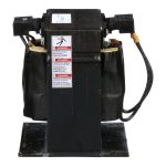
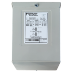
GP Enclosed Series – 250 VA to 2000 VA
Open-frame transformers rely on the host enclosure for protection. The GP Enclosed Series integrates the transformer into its own dedicated NEMA-rated housing for installations where the unit is mounted externally, in washdown areas, or in dusty environments. Primary: 208–600 V. Secondary: 120/240 V. Available in NEMA 3R.
- VA range: 250–2000 VA
- Primary voltage: 208–600 V
- Secondary voltage: 120/240 V
- Enclosure ratings: NEMA 3R (corrosion-resistant)
- Frequency: 60 or 50/60 Hz (depending on model)
- Listing: UL/cUL 5085-2, CE marked
- Best for: Outdoor mounting, washdown facilities, harsh industrial environments, external panel mounting
Series at a glance:
| Feature | GP Standard Series | GP Econoline Series | GP Enclosed Series |
| VA Range | 25–2000 VA | 300–1500 VA | 250–2000 VA |
| Primary Voltage | 120–600 V (multi-group) | 120–600 V (multi-group) | 208–600 V |
| Secondary Voltage | 12–240 V (group-dependent) | 12–240 V (group-dependent) | 120/240 V |
| Insulation Class | B, F, H, N (130–200 °C) | F (155 °C) | F (155 °C) |
| Frequency | 50/60 Hz | 50/60 Hz | 60 or 50/60 Hz |
| Warranty | 10 years | 10 years | 10 years |
| Listing | UL/cUL 5085-2, CE | UL/cUL 5085-2, CE | UL/cUL 5085-2, CE |
| IEC Touch-safe Terminals | Yes | Yes | Yes |
| Best For | All standard panel builds | Budget-conscious OEMs | Harsh / external environments |
Not sure which series fits your project?
Powervolt Group’s engineering team can specify the right transformer — or design a custom solution — for any voltage, VA, or environment requirement.
→ Request a Quote or Talk to an Engineer →
3. Voltage Groups and Part-Number Families
Every GP Series transformer is identified by a voltage group letter that defines the primary and secondary voltage combination.
The part number structure is: GP[VA]-[Group][00]. For example, GP0500-A00 is a 500 VA transformer in Group A (220/440, 230/460, 240/480 V primary → 110/115/120 V secondary).
The most commonly specified group is A00 – covering 220–480 V primary to 110–120 V secondary, available in all 14 VA ratings from 25 VA to 2000 VA.
For a full breakdown of every A00 model with inrush derating curves and dimensional drawings, see the GP Standard A00 Series guide.
| Group | Primary Voltage |
| A | 220/440, 230/460, 240/480 V → 110, 115, 120 V |
| B | 230, 460, 575 V → 95, 115 V |
| C | 480 V → 240 V |
| D | 600 V → 240 V |
| E | 208, 230, 460 V → 115 V |
| F | 550, 575, 600 V → 110, 115, 120 V |
| G | 380, 415 V → 110/220 V |
| H | 208, 277, 380 V → 120 V |
| J | 240/480 V → 24 V |
| K | 120/240 V → 24 V |
| M | 240/480 V → 120/240 V |
| EJ | 120–600 V (select inputs) → 24, 115 V (Configurable) |
| EG | 120–600 V (select inputs) → 115/230 V (Configurable) |
| EB | 120–600 V (select inputs) → 85, 130 V (Configurable) |
Need a non-standard voltage? Use Powervolt Group’s Cross-Reference Tool or contact the factory for a custom configuration.
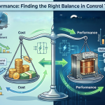
4. VA Sizing – Choosing the Right Capacity
Selecting the correct VA rating is the most critical design decision. Undersizing causes secondary voltage to sag during inrush — triggering relay drop-out or PLC faults. Oversizing wastes cost and panel space.
Step 1 – Catalogue every secondary load
List every device powered from the 120 V control circuit: contactor coils, relay coils, solenoid valves, PLC power supply, I/O modules, HMI panels, pilot lights, and timers. Record both steady-state (sealed) VA and inrush VA for each.
Step 2 – Calculate worst-case simultaneous inrush
Identify the moment when the most coils energise at once — typically machine start-up. Powervolt’s catalogue provides two calculation methods: (A) √(VA sealed² + VA inrush²), or the simpler (B) VA sealed + VA inrush.
Method B produces a slightly oversized result, which is the safer default. Electromagnetic devices typically energise in 20–50 ms and draw 3–10× their sealed current.
Step 3 – Apply the Regulation Data Table
Adjust for supply voltage tolerance. If the line voltage is stable within ±5%, use the 90% secondary voltage column.
If it varies up to ±10%, use the 95% column. NEC and most device standards require reliable operation at 85% of nameplate voltage — use the 85% column for worst-case specification.
| VA Rating | Inrush VA @ 40% PF — 85% Secondary |
| 25 VA | 160 VA inrush |
| 50 VA | 270 VA inrush |
| 75 VA | 435 VA inrush |
| 100 VA | 655 VA inrush |
| 150 VA | 1,300 VA inrush |
| 200 VA | 1,975 VA inrush |
| 250 VA | 2,680 VA inrush |
| 300 VA | 3,180 VA inrush |
| 350 VA | 3,665 VA inrush |
| 500 VA | 6,300 VA inrush |
| 750 VA | 10,555 VA inrush |
| 1000 VA | 15,225 VA inrush |
Select the VA rating that is closest to – but not less than – both your total sealed VA and your total inrush VA.
GP Standard A00 Series – VA quick-reference (Group A: 220–480 V primary → 120 V secondary):
| VA | Part No. | Primary | Typical Load | Application |
| 25 VA | GP0025-A00 | 220–480 V | Pilot lights, small relays | Indicator panels, annunciators |
| 50 VA | GP0050-A00 | 220–480 V | Single contactor + pilot lights | Simple motor starters |
| 75 VA | GP0075-A00 | 220–480 V | Multi-contactor, light duty | Light-duty starter panels |
| 100 VA | GP0100-A00 | 220–480 V | PLC + I/O modules | Programmable control panels |
| 150 VA | GP0150-A00 | 220–480 V | Multi-relay + HMI display | Mid-complexity automation |
| 200 VA | GP0200-A00 | 220–480 V | Motor starters, panel boards | Combination starter panels |
| 250 VA | GP0250-A00 | 220–480 V | Multiple solenoids + relays | VFD + PLC + I/O panels |
| 300 VA | GP0300-A00 | 220–480 V | Large panel boards | Multi-axis control panels |
| 350 VA | GP0350-A00 | 220–480 V | Heavy relay logic panels | Complex relay logic systems |
| 500 VA | GP0500-A00 | 220–480 V | Machine tool control circuits | CNC and machining centres |
| 750 VA | GP0750-A00 | 220–480 V | Automation systems, conveyors | Full MCC bucket applications |
| 1000 VA | GP1000-A00 | 220–480 V | Large machine control panels | SCADA + dual PLC systems |
| 1500 VA | GP1500-A00 | 220–480 V | Heavy industrial automation | Robot cells, stamping lines |
| 2000 VA | GP2000-A00 | 220–480 V | High-load plant infrastructure | Central automation rooms |
Full spec sheets, inrush derating curves, and dimensional drawings for each model are in the GP Standard A00 Series Guide.
Size to inrush, not steady-state
The most common sizing mistake is calculating only the steady-state load. A 100 VA transformer will sag below 85% secondary voltage when three contactors energise simultaneously at start-up. Always base your VA selection on the inrush budget.
5. Key Specifications to Evaluate
- Primary voltage – must match your available line voltage; Powervolt’s configurable EJ/EG/EB groups accept any input from 120 to 600 V
- Secondary voltage – confirm all control devices are rated for the transformer output voltage
- VA rating – sized to handle worst-case simultaneous inrush per Section 4
- Insulation class – Class B (130 °C) standard; Class F (155 °C) for Econoline; Class H (180 °C) or N (200 °C) available in GP Standard for high-ambient environments
- Mounting style – open-frame panel mount (Standard and Econoline) or NEMA-enclosed (Enclosed Series)
- Certifications – UL/cUL 5085-2 (File E47299), CE marked; meets/exceeds NEMA ST-1, ANSI, NMBTA, and JIC
- Frequency – 50 Hz, 60 Hz, or 50/60 Hz dual-rated
- Fuse options – optional CC-class or slow-blow fuse blocks; fuse block kits available for field installation
- Mounting compatibility – Siemens, Micron, and Hammond mounting-compatible variants available on Standard Series
6. Installation and Wiring Best Practices
Primary circuit
De-energise and lock out the upstream panel before wiring. Connect primary leads to a dedicated fused disconnect sized with slow-blow fuses at 200% of the transformer’s rated primary current.
Do not share primary conductors with other loads. Select the correct primary tap terminal for your line voltage – Powervolt’s Group A units, for example, offer 220/440, 230/460, and 240/480 V tap positions on the same unit.
Secondary circuit
Protect the secondary with control-circuit fuses or a breaker rated at 200% of rated secondary current — per NEC Articles 430 and 725.
Keep secondary runs short to minimise resistive voltage drop during inrush. Powervolt’s optional fuse block kits (CC-class or slow-blow) allow a clean, code-compliant installation.
Grounding
Ground one secondary terminal (typically X2) to the panel ground bus per NEC 250.186. Isolated secondaries may be required by NFPA 79 on certain machinery – confirm with your safety engineer before omitting the ground connection.
Ventilation and clearance
Maintain at least 25 mm clearance on all sides for natural convection. Do not mount directly above VFDs or braking resistors.
For Class H or N insulation variants in high-ambient locations, apply the manufacturer’s thermal derating curve. Powervolt’s GP Enclosed Series units handle environmental protection internally – verify NEMA rating matches the installation category.
⚠️ Safety – First Energisation Check
After initial wiring, verify secondary voltage under load within the first 30 minutes of operation. If case temperature exceeds 60 °C above ambient, de-energise immediately and inspect for overload, open fuse, or wiring fault.
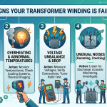
7. Troubleshooting Common Faults
| Symptom | Likely Cause and Remedy |
| Low secondary voltage under load | Transformer undersized for inrush – upgrade to the next VA rating, or use a separate transformer for high-inrush loads. |
| Transformer running hot | Secondary overload, inadequate ventilation, or ambient temperature exceeds class limit – check VA draw and apply derating curve. |
| Audible hum or vibration | Core laminations loose (check mounting torque) or DC component on primary from upstream rectification. |
| Primary fuse blowing on energisation | Inrush current exceeds fuse rating – switch to slow-blow (time-delay) primary fuses at 200% of rated primary current. Powervolt offers CC-class and slow-blow fuse block options. |
| Correct voltage but relay drops out | Secondary voltage sags during contactor inrush – transformer undersized; re-calculate inrush load per Section 4 and upgrade VA. |
| Transformer hot in enclosed panel | Insufficient ventilation – ensure 25 mm clearance, or upgrade to GP Enclosed Series with NEMA-rated housing for temperature-controlled environments. |
8. Applicable Standards and Certifications
Powervolt Group’s GP Series transformers carry the following agency approvals (UL File E47299):
- UL/cUL 5085-2 – Standard for General Purpose Transformers (Low Voltage), North America
- CE Marking – LVD 2014/35/EU (required for European market access)
- NEMA ST-1 – voltage regulation requirements (GP Series exceeds this standard)
- ANSI and NMBTA – applicable American national and industrial standards
- JIC – Joint Industry Conference panel-wiring standards
- NEC Articles 430 / 725 – US installation requirements for motor and control circuits
- IEC 61558-2-2 – International safety standard for general-use transformers
9. Frequently Asked Questions
What is the difference between a control transformer and a power transformer?
Power transformers are optimised for efficiency at sustained rated load. Control transformers are engineered for inrush withstand – they maintain ≥ 85% secondary voltage during a momentary 3–10× overload at the cost of some continuous-load efficiency.
They also have higher thermal mass and leakage reactance, which limits short-circuit current and protects downstream control devices.
What makes Powervolt Group’s transformers different?
Powervolt Group has manufactured transformers since 1973 and operates from a 30,000 sq. ft. facility in Addison, Illinois.
All products are 100% tested before shipment, supported by a 10-year warranty, and available with 3-day standard shipment for in-stock models.
The configurable EJ/EG/EB voltage groups allow a single SKU to serve multiple international supply voltages, reducing OEM stocking complexity.
Which Powervolt series should I specify for a standard North American 480 V panel?
For a 480 V primary to 120 V secondary application, specify the GP Standard Series, Group A (GP[VA]-A00). Available in 14 VA ratings from 25 VA to 2000 VA. For a detailed part-by-part comparison, see the GP Standard A00 Series Guide.
Can one control transformer serve multiple machines?
Not recommended. A fault on one machine’s secondary circuit affects all machines sharing the supply. Best practice is one transformer per machine or per isolated control zone, with independent secondary fusing on each circuit.
How do I calculate VA for a contactor coil?
Multiply the sealed (steady-state) VA by the inrush ratio (typically 3–10×, available from the device manufacturer). Sum all simultaneously closing coils. Confirm against Powervolt’s regulation data table in Section 4. Contact Powervolt’s engineering team for free sizing assistance — see CTA below.
Does Powervolt Group offer custom configurations?
Yes. Powervolt Group’s engineering team designs custom transformers to meet specific voltage, VA, insulation, footprint, or certification requirements. Custom designs are prototyped and fully tested in Addison, Illinois before shipment. Contact [email protected] or call (630) 628-9999.
10. Browse Products and Get a Quote
All three GP Series lines are in stock at the Addison, Illinois facility with 3-day standard shipment. OEM contracts and volume discount programmes are available.
- GP Standard Series (25–2000 VA, all voltage groups) — the flagship open-frame line
- GP Econoline Series (300–1500 VA, Class F insulation) — cost-optimised for budget OEM builds
- GP Enclosed Series (250–2000 VA, NEMA 1/4/4X) — for harsh or external environments
- GP Standard A00 Series Guide — deep-dive on every 220–480 V to 120 V model
- Cross-Reference Tool — find Powervolt Group equivalents for Acme, Hammond, Micron, and Square D part numbers
Get a Quote — Same-Day Response
Submit your VA, voltage, and quantity requirements and a Powervolt Group engineer will respond within one business day. OEM pricing, stocking programmes, and custom designs available.
Contact Powervolt Group: | [email protected] | (630) 628-9999 | 300 W Factory Road, Addison, IL 60101